I couldn’t work on the van until the afternoon today and I dove into making sure the lights were installed correctly. I picked up a small 12V battery so I could test the wiring we did yesterday and finish the other four lights today. Unfortunately, my testing showed the stupid splice connectors we used suck. I had feared this a little because I don’t think the wire coming from the lights is the same gauge as the 18ga wire running from the lights to the switch. Sure enough, the light that was spliced in with the connector did not work.
We have two sets of four lights and each will be controlled with its own 12V LED dimmer switch. The four lights over the bed will be switched on the driver wall behind the refrigerator. The four lights over the galley will be switched on the passenger wall behind the stove.
So, each pair of lights at the same point in the van get connected with a wire running across the van and then those two wires get connected before the switch. This means I need to splice one light into the other for each pair and then one set of two lights into the other set of two lights. Three splices total.
In some of my sleepless hours last night I had watched a YouTube video on how to splice wires inline to existing wires. I figured that technique would work. It isn’t that hard and I am pleased with the results. I used the technique for both pairs of lights and then to join the two pairs to form the 4-light set.
Here is how it works using. These pictures show the last splice joining the two wires that each feed two lights. This splice is in the middle of the SO cord (insulated wire pair) so I had to remove the insulation and then strip the wire.
Step 1: Buy a new stripping tool that can strip wires in the middle of the wire. Fortunately I was able to get one on my first trip of the day to Ace.
Step 2: Strip a section of wire in the place where you want to add your incoming wire. In this picture I have also already stripped/removed a section of the insulation. It would have been a bit easier if I had stripped a little more insulation.

Step 3: Use something pointy to carefully divide the wires in half.

Step 4: Strip a good 1.5″ on the wire you are going to splice in. Insert that exposed wire into the gap you created.

Step 5: Hold the two wires together and tightly wrap the end of the wire around the area of stripped wire you exposed. Here I have already wrapped the negative and partly wrapped the positive.

Step 6: Wrap it up in good electrical tape. The internets recommended at least three wraps. You can solder the connection if you want, but this method does make a very strong connection. I messed up a few of the wires on one of the splices (not pictured!) so I did add solder. Of course, I barely know what the heck I am doing using solder so it is not all that likely I improved my splice!

Step 7 (Optional): If you have access to one of the ends of the wire you can slide some shrink tubing over the connection.

You can see I did the same thing to add the lights. It seems like an especially good technique for joining two wires when they are not exactly the same size. Because I was also connecting two wires here using butt connector I slid some shrink tubing on these as well.

Boom! Lights!
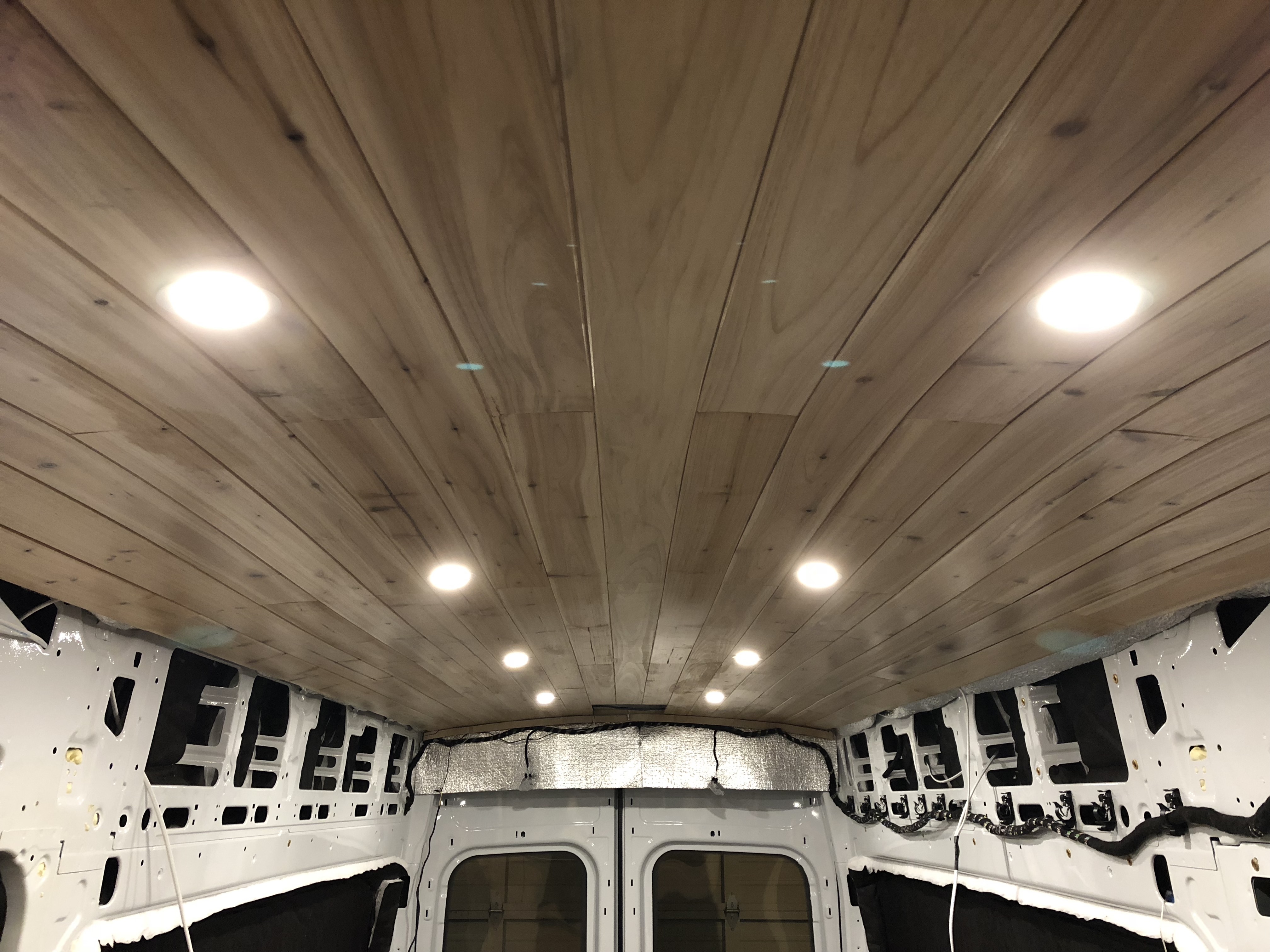

It is really coming together nicely! Great pictures!